(2020-06-08) PE1ITR
Since 2006 I have built a dxalert system to warn me when special radio propagation occurs on the VHF bands. This system is built on the tables filled by the software application
LIVE_MUF. A lot of own functionality has been added over the years. It is now 2020 and time to redesign the software of this E-skip alert system.
I have a big database and from the year 2000 all E-skip openings are stored in this database. Enough data to create an improved algorithm that recognizes patterns to alert me. This page describes the conditions that the system uses for the E-skip warnings. It is about the characteristics of E-skip propagation at 144 MHz and not about the explanation why this type of propagation sometimes occurs.
Analysis of the database data shows that the geometry of the QSO's and the derived MUF value is a good indicator of whether E-skip radio propagation is possible. The MUF in the reflection area for the 1st hop should be sufficiently high. However, that is not enough. The geometry must also be correct. It turns out that my QSO capabilities should not deviate more than 2 degrees about the axis of other QSO's that are logged.
It seems that E-skip propagation always occurs in the afternoon usually between 16:00 and 18:00 UTC. However, this is not a characteristic of this type radio propagation, but rather a characteristic when stations are QRV. It also turns out many openings are in the morning and even sometimes at night. The time of the day does not matter in the warning system.
User perspective
From a user perspective, I define the following need for information:
- I want to receive a warning message when there is E-skip on 144 MHz that I can use from my location.
- I want to be able to call up a continuous overview on which I can see how high the MUF is, in which direction it is and whether there are propagation possibilities for my station.
- When I get a warning I want to see in which direction I should put my antenna.
- When I receive a warning I want to see which areas I can receive or reach. The locator gridquare is sufficient.
- I also want to be able to see for each locator gridsquare which stations can be on 144 MHz QRV.
- Not too much information on the screen
1st Hop
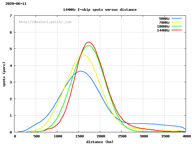
In the graph below, the red line shows the distribution of the number of 144 MHz connections compared to the distance for single hops. Most E-skip QSOs at 144 MHz are over a distance of 1750 km. I suggest that most connections are made over distances between 1300 and 2400 km. The reflection area between the stations must then be between 650 and 1200 km. One condition is that the MUF must be sufficiently high at a distance of 650 and 1200 km.
2 degrees over the Axis
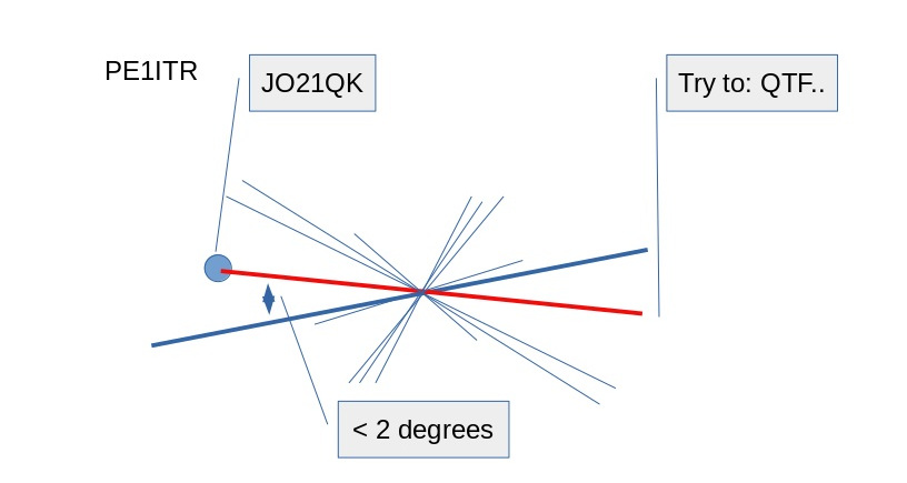
The sketch below shows the situation as we often see it. QSO's made between stations are indicated by a blue line. These lines create a kind of cross, which we assume is the reflection area in the middle. Here the MUF must be high enough to reflect / bend the 144 MHz signals.
In addition, it also turns out that from my position I often only work stations where the antenna direction differs by 2 degrees at most. There seems to be a short-lived narrow corridor from my location in which QSO's to certain locations succeed, but not outside this corridor. The situation is different for other stations.
With this finding, you could say that from a location there are only QSO's options if you also see other QSO spots on the same axis. The deviation over this axis is set at a maximum of 2 degrees. The software takes advantage of this by comparing the axis of each spot to the axis from my location. Take into account the distance from the reflection area to my location and the MUF value in that reflection area.
In the software the red line is calculated and fed back to the user with the text try in the direction QTF 'n' for station in the locator gridsquare 'x'. For example, Try to QTF 140 for JN90.
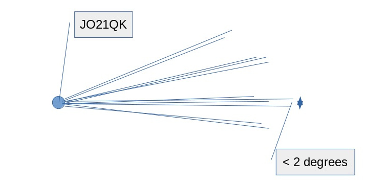
Below a picture with in fact the same situation, but now seen from 1 station. When QSO's are made over a certain period of time during an opening, you see that seen in time these QSO's most of the situation form groups. The min and max QTF of such a group often differs no more than 2 degrees in azimuth.
Explanation information screen
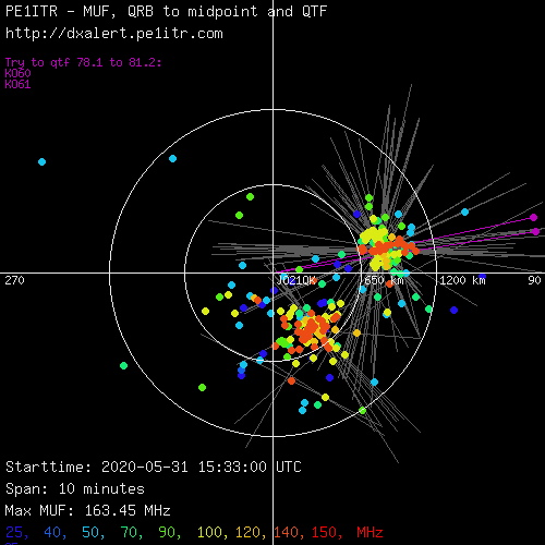
Below is an example of the information screen during the E-skip opening of 2020-05-31. The screen has a compass shape with my location in the middle (JO21QK). Two white circles are shown. The inner circle at 650 km and the outer circle at 1200 km. The reflection area should be between these two circles.
LIVE_MUF calculates the MUF of each spot in the middle between the stations. In the screen below, only the position of this center is shown as a dot. The dot color represents the maximum MUF. At the very bottom you can see which color corresponds to which frequency in MHz. When there is a real opening, a collection of the dots is created. When these dots turn red, the MUF is high enough. And when this collection of dots is also gathered between the circles, it becomes interesting for the DX.
When the MUF> 100 MHz, faint gray lines are also drawn between the station. This was done to give an idea of what the 'X' shape looks like.
When a faint gray line spans the axis within two degrees of a line from my location and the MUF in the centerpoint is > 140 MHz, the color of this line changes from gray to white. In this situation also a new purple line is immediately drawn from my position with the center over the reflective area. The other end of the purple line is then the area with which a theoretical QSO can be made. This results into the 'Try to QTF .." information and a warning message is sent out.
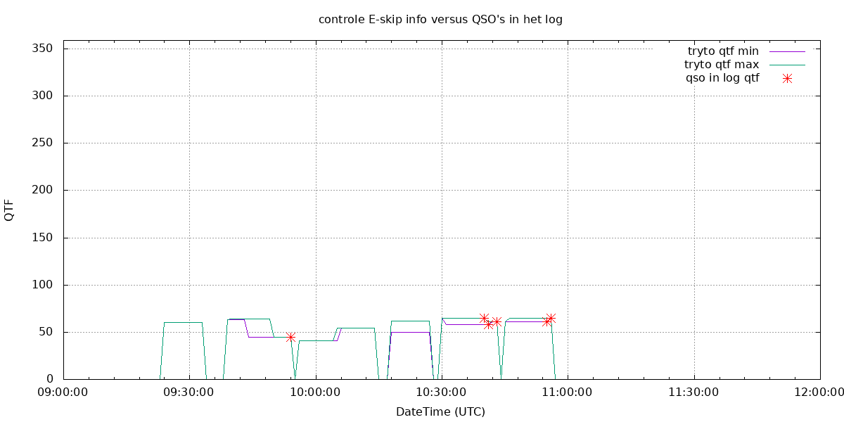
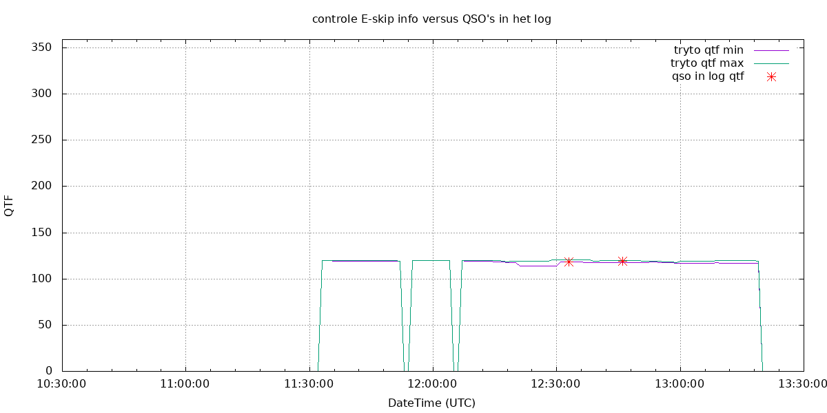
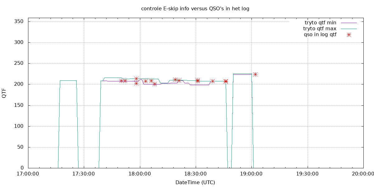
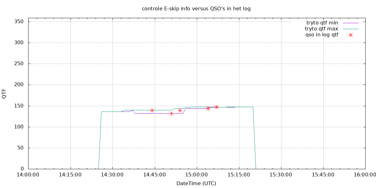
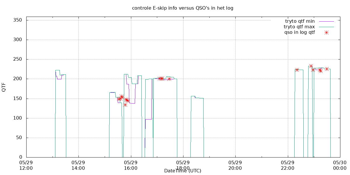
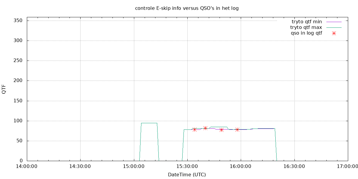
Comparison with the predictions with the qsolog
For a number of openings I checked the 'Try to ..' calculation with the QSO's in my log. At the moments when E-skip is predicted (the purple line is then visible) I have compared the min and max QTF information against the QTF in which I actually made a QSO. The result is good reliability of the forecast.
Opening 2010-06-02
A spotty opening towards North-East.
Opening 2012-06-09
An opening with a narrow corridor, the reflection area of which slowly shifts to the west. This shift to the west is seen more often, but it is not always the case.
Opening 2013-06-09
Opening 2015-07-08
Opening 2020-05-29
Opening 2020-05-31
This is an interesting opening because initially Dutch stations worked with Italian stations. However, I was unable to receive these stations. The reflection area was too close to my location. This also shows the animation. Later the band opened for me to KO60 resulting in 4 QSO's. This opening can also be seen in the animation.
This is the main query that gets the data from the tblspot table
select fqrb(left(a.tryfrom,6),a.dxloc1) as km1, fqtf(a.left(tryfrom,6),a.dxloc1) as hoek1, fqrb(left(a.tryfrom,6),a.dxloc2) as km2, fqtf(left(a.tryfrom,6),a.dxloc2) as hoek2,
	fqrb(left(a.tryfrom,6),left(a.tryto,6)) as km3, fqtf(left(a.tryfrom,6),left(a.tryto,6)) as hoek3, left(a.tryto,4) as grid,
	case when a.qtf1 > 180 and a.qtf2 < 180 then abs(a.qtf1 - 180 - a.qtf2)
	when a.qtf1 < 180 and a.qtf2 > 180 then abs(a.qtf1 + 180 - a.qtf2)
	else abs(a.qtf1 - a.qtf2) end as hoek
	from tblspot a
	where a.DxDateTime > subdate(utc_timestamp(),interval $span minute)
	and a.qrb_to_midpoint between $ringbinnen and $ringbuiten
	and a.muf >= 100 having hoek < 2;