144MHz OWL Antenna
(2017-07-30) PE1ITR
OWL = Optimised Wideband Low Impedance. I first read about OWL in 2011 on the G0KSC website.
Somewhere in 2014 I wanted to build a new set of 144MHz antenna's. The boom length had to be around around 4.5 meters long because the antenna had to fit in my garden. I had made several designs already but this time I searched for a more modern
design that could be used as all-round yagi for contesting (short antenna, beamwidth around 37 degrees), EME (Good gain and good G/T), Meteor scatter, tropo, etc.
For my situation the important parameters where: 1. Boom Length, 2. Gain, 3. G/T.
Somehow I was attracted to the 12.5 ohm impedance antennas.
On this page I describe my experiments with this antenna. New findings or adjustments will change this page.
Antenna Selection
First I selected 12 antennas designs I found on the internet. I calculated the gain in NEC4. I calculated the G/T in Tant by exporting the pattern from NEC4.
The boom length is more or less a constant value for my situation. In the last graph I combined the Gain and G/T. From this graph I found that the 9el 28 ohm DK7ZB and the 9el G0KSC 12.5 ohm owl where the most interesting designs.
The 9el DK7ZB also came as a candidate. By chance I have 2 of these types of antennas for over ten years and I am very pleased with their performance.
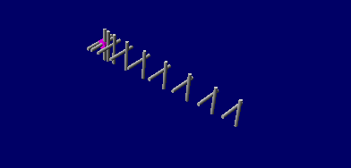
I decided to build the 9el G0KSC 12.5 ohm owl yagi design.
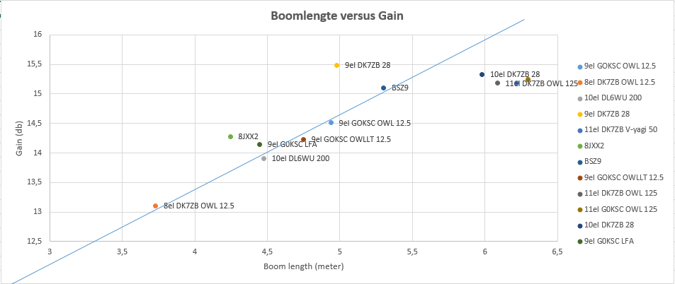
Fig 1:
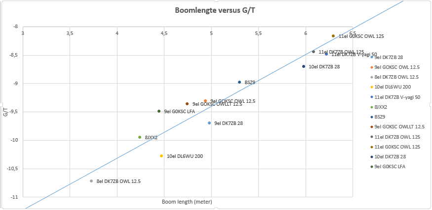
Fig 2:
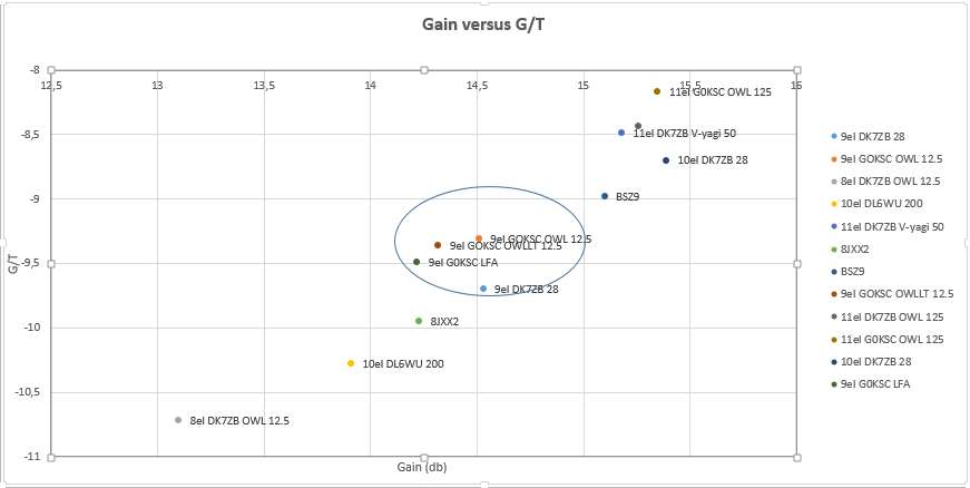
Fig 3:
Pattern, SWR
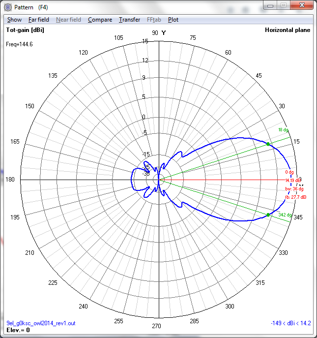
Fig 4:
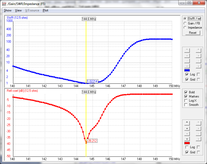
Fig 5:
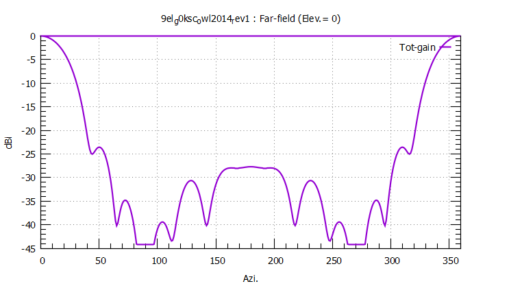
Fig 6: When the pattern is normalized the front/back ratio is showed
Building the antenna
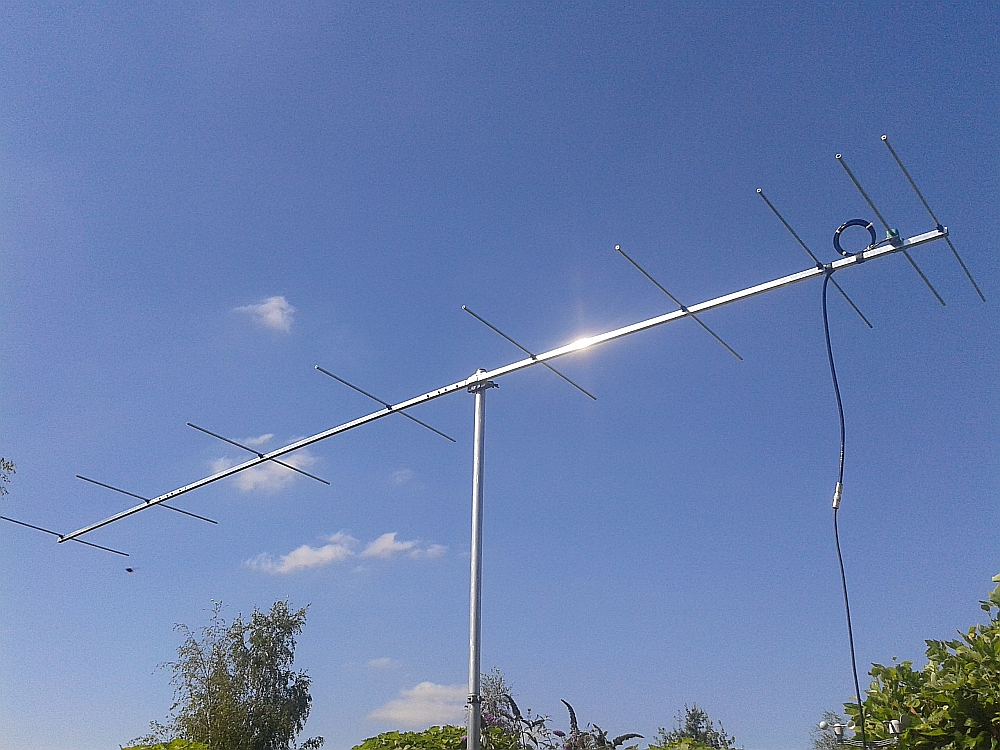
Fig 7: First version a few days before the 144MHz september 2014 contest. We used a stack of 3 yagi during this contest
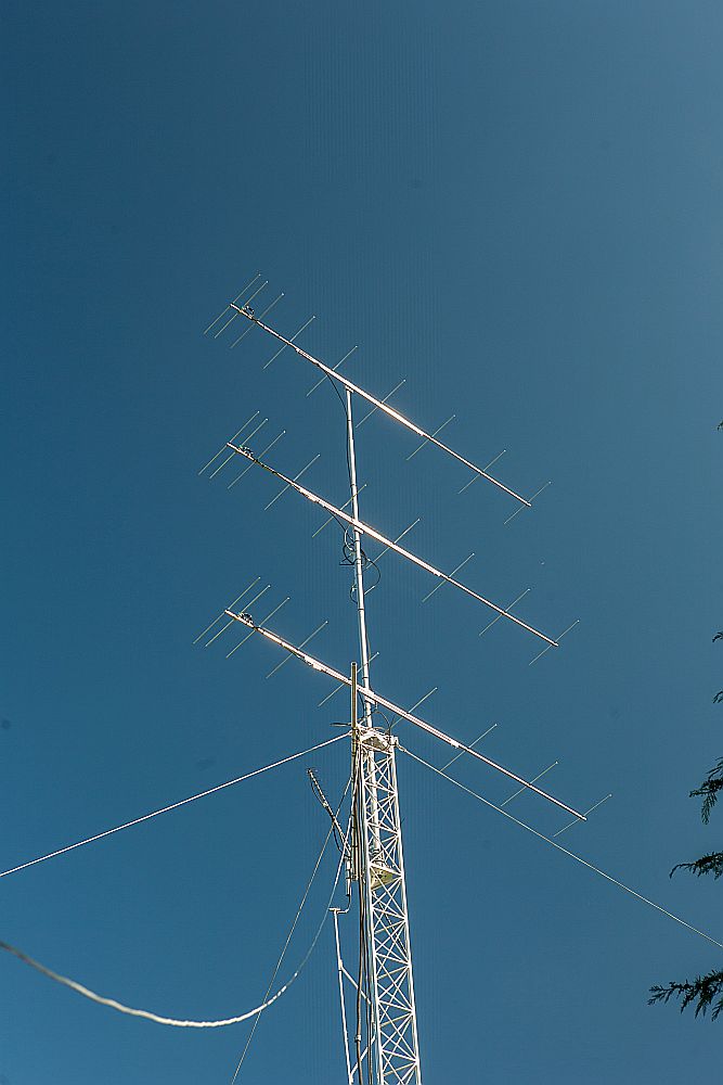
Fig 8: Stack of 3x 9el OWL yagi antenna's. VHF Marconi Memorial november 2014.
Transformator and Feeding the dipole
The antenna has an impedance of 12.5 ohms.
The transformation from 50 ohm to 12.5 ohm impedance is made with a quarter-wave 25 ohm coaxial piece.
In the first version I made the transformer of two-quarter wave piece of aircell5 coax of 50 ohms in parallel. This worked fine. At the time the dipole was open.
I noticed corrosion on the 4mm screws with which the balun was connected to the dipole.
And the mechanical construction of the coaxial transformer was not suitable for frequent construction and breakdown of the antenna's.

Fig 9: Dipole connection.
Later I made the dipole connections in a box.
The coax was then replaced by a quarter-wave teflon KTR141 coax of 25 ohm impedance.
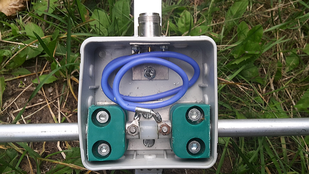
Fig 10: Dipole connection in a box. Blue coax is 25 ohm KTR141.
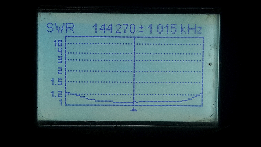
Fig 11:
Converting antenna to X-POL
I usually am qrv on EME with two of the 9el owl antennas.
The two antennas are stacked and only horizontally or vertically polarized.
In this way I could work with some effort also the smaller dxpedition EME stations.
However, because it was single polarized, I was often excluded from signals.
The need arose to go to adaptive polarization. I wondered if I could convert this existing antenna to an x-pol
antenna.
This project has stood still for a long time until resumed in 2020. This is described on this page.
HOME | Go Back