VHF Radar Experiments Airplane Backscatter
(2020-11-07) PE1ITR
On this web page I wrote about reflections against meteors. I also receive echoes from airplanes. Some notes on this on this page.
I sometimes noticed strong reflections from airplanes as they pass about 80 km away. These backscatter reflections are strongest when they come from the side of the aircraft. I will explore this situation further on the basis of an example.
Example Event
In this example, an airplane is passing by and flying towards 290 degrees azimuth. The 10 elements yagi is facing 200 degrees. This optimally illuminates the side of the aircraft. I have chosen a time during the night when there is little air traffic. This is to unambiguously determine the correct aircraft. The radar is operating on 144.510 MHz.
To confirm the correct aircraft, I also receive the forwardscatter against this aircraft from the 2m beacon F1ZXK. F1ZXK is on 144.437 MHz and has locator JN18AS. The direction of the beacon is 220 degrees azimuth and the distance 380 km.
Some time after the radar backscatter echo's have been received, the forward scatter of the beacon must therefore occur.
Below 4 images with successively the backscatter reflection and then the forward scatter reflection.
The aircraft passes approximately at a distance of 65 km at an altitude of approximately 10 km.
At 144.510 MHz the backscatter reflection from the radar transmitter.
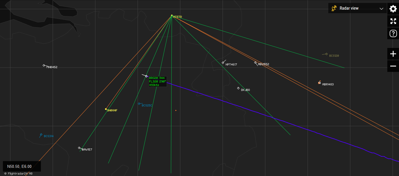
The situation during the backscatter.
And 1.5 minutes later at 144.437 MHz the forwardscatter reflection from the beacon.
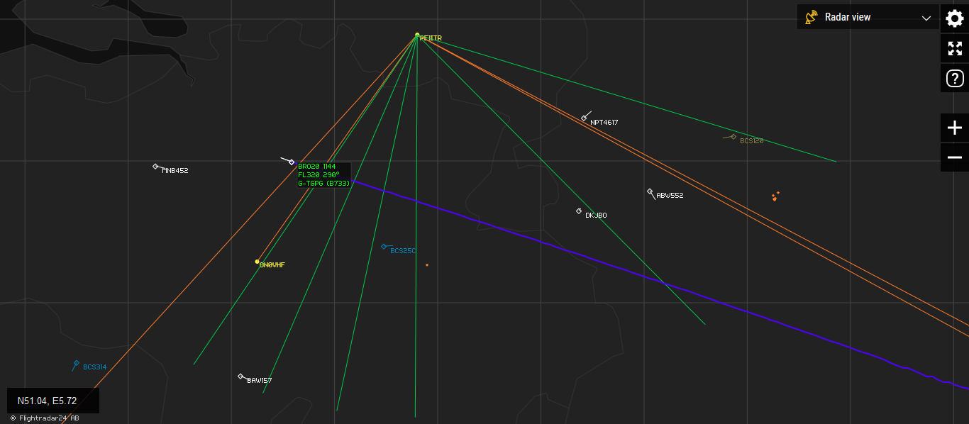
The situation during the forwardscatter.
Signal strength
Backscatter signals are not as strong as forward scatter signals. The strength of the backscatter signals depends on the Radar Cross Section (RCS). The RCS can be seen as the reflective power of an object expressed in m2. The RCS depends on many factors such as the type of material, the size of the object as you see it as an observer, the angle of incidence and so on.
From the literature, the RCS of a normal airliner varies from 6 m2 to 350 m2 depending on who you look at it. The highest RCS value is when you look at the side of the aircraft.
The amount of reflected power can be calculated by the following formula: Pr = (Output power * antenne gain / (4 * PI * Distance^2)) * RCS * (antenne gain / (4 * PI * Distance^2))
When I assume the following parameters and the radar antenna is perpendicular to the airplane : Output: 400 watt, Antenna gain: 10 db, Distance to airplane: 75 km, RCS minimal 6 m2 and maximum: 350 m2.
Then the reflected signal level varies between -133 and -116 dbm. This is a difference of 17 db. it is therefore important for the small system to look at right angles to the plane. This is confirmed by the observation.
The signal strength of the echo over time has intriguing patterns. It is a little different for every airplane or situation. Characteristic is that the signal is strongest when the antenna is exactly perpendicular to the plane. Furthermore, there are deep zeros as if signals cancel each other out as a result of an interference pattern. Below a picture with an example of this. The time axis runs from left to right. The signal strength is the intensity of the green.
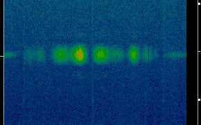
interference pattern as received
In the literature I have read that certain parts of an airplane are more shiny than others. For example the engines and the tail, or fuselage at the front are very shiny. If so, there are multiple sources on a baseline where the echo is coming from. Multiple signal sources on a line produce an interference pattern.
I simulated this by displaying the pattern when two signal sources pass 30 meters apart on a line at a speed of about 900 km per hour. This is of course a very simplified representation of reality. The pattern that arises is very similar to the signal strength of the echoes over time.
It shows that the nice signal strength patterns are caused by the aircraft itself. When the baseline decreases, the oscillation frequency increases. When the baseline increases, the oscillation frequency decreases. In reality, the interference pattern is of course much more complex and we see the addition of several interference patterns.
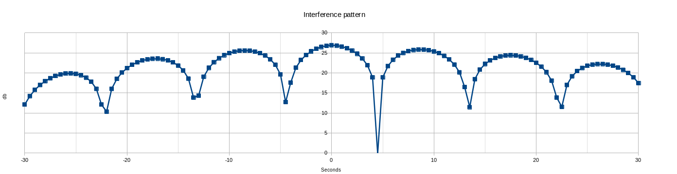
simplified simulation of the interference pattern
Distance
With meteor reflections I was able to calculate the distance to the object nicely. This is more difficult in my system for airplane reflections. This is because the distance between radar and object is very small. The looptime has then become so small that we are running up against limits of the system to measure accurately. The system as it is now is not suitable.
Assuming the plane was 65 kilometers away, the looptime would have been 434 microseconds. The end of a transmit pulse and start of reception is set at 25 micoseconds. So a theoretical puls of 409 microseconds is received from the returning 4 ms puls.
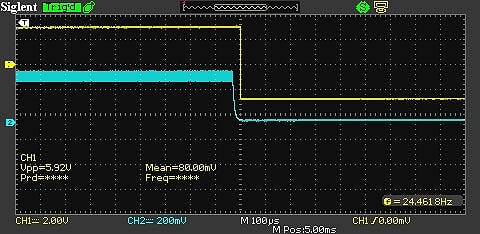
TX to RX switch
I measure a pulse of 33 samples. This corresponds to 683 microseconds, which would mean that the distance of the aircraft must have been at least 103 km. Of course, this is incorrect because we know how far the plane was in reality. In addition to the inaccuracy, there are even more lingering effects. In any case, the system needs to be characterized even better when it comes to the switch from transmitting to receiving. I think the inaccuracy is 50 km.
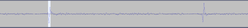
Received puls 33 samples
HOME | Go Back