QO-100 / 'Es-hail2
(2019-11-13) PE1ITR
On February 12, 2019, I made my first qso on the narrowband transponder of the geostationary QO-100 amateur radio satellite.
I have since been active in a changing setup on this satellite on the Narrowband transponder with Phone / Digital modes and the Wideband Transponder with DATV.
On this page I describe parts of my station. It is primarily intended as documentation for myself, but this may help others to build their station.
The up and down link frequencies, the associated bandplan and the user guidelines can be found on the website of the Amsat-DL.
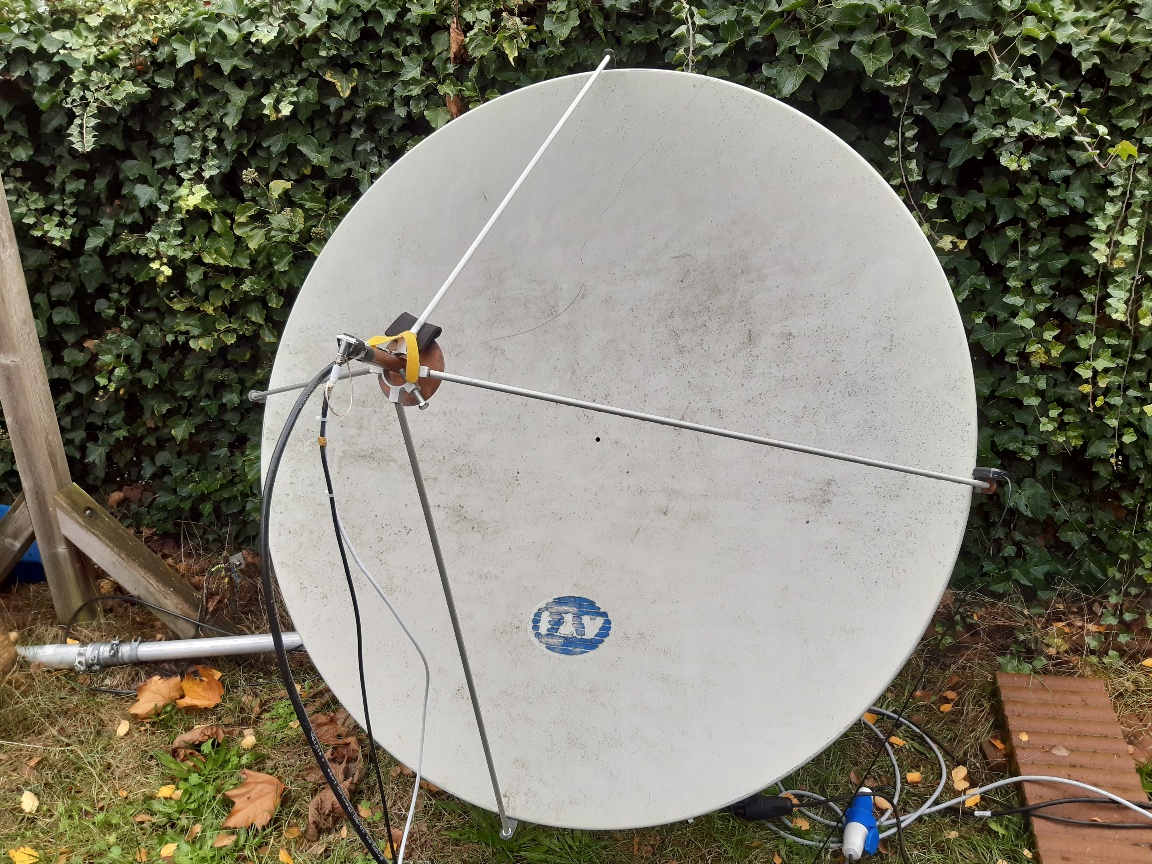
Dish and feed
I have a dish antenna of 144 cm diameter. The depth is 18 cm.
The focal point can be calculated with the formula (diameter) ^ 2 / (16 * depth). The values entered results: 144^2 / (16 * 18) = 72 cm.
Due to inaccuracy in the measured values, the focal point can be between 71 and 72 cm. By shifting the LNB I have established that the focal point is somewhere between 71 and 71.5 cm.
This maximum is not very sharp. This is measured from the tube of the feed to the dish. Assuming that the actual focal point is a few mm in the feed tube, this could be correct.
The F/D of this dish is 72 / 144 = 0.5
On 10 GHz this dish has a 3db beamwidth of 1.3 degrees, antenna gain 42 db. On 2.4 GHz this is 6 degrees, antenna gain 30 db.
From a graph presented at the Amsat-DL annual meeting on November 9, 2019, the noise level of the narrowband transponder with this dish should be 7 db higher than the cold sky noise.
I measure 6 db noise. Als from the DATV side I am 1 to 1.5 db short of what to be expected.
For my location, and according to the BATC Calculator the dish needs to be aligned to: Azimuth: 154.6 degrees (153 magnetic), Elevation: 28.1 degress. LNB Skew: -15.5 degrees.
My satellite track program shows also Azimuth: 154.6 degrees, Elevation: 28.1 degrees. Range 38770,0 km. Based on Kepler element catalog number: 43700.
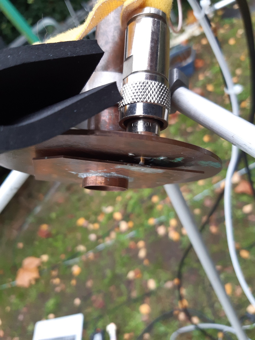
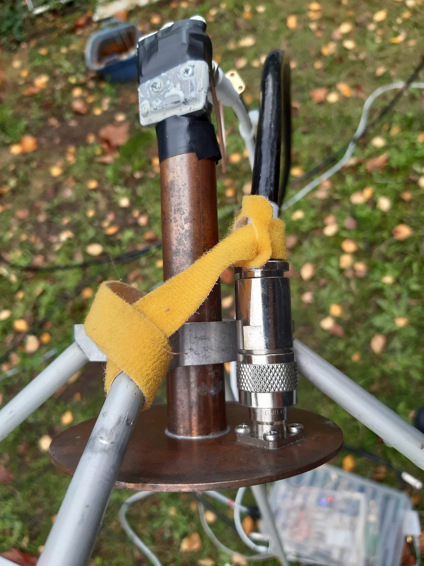
A POTY feed is used.
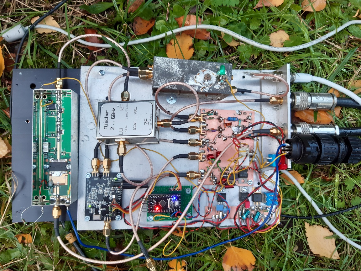
Transverter
Description of the transverter.
Starting from an FT817 tranceiver, a send signal at 432,600 MHz goes to the transverter. This is mixed with an LO from 1967.5 MHz to 2400,100 MHz. With a PA3AXA 50db amplifier this goes to the dish feed.
For reception, a 10489.6 MHz signal in the LNB with a LO of 9750 MHz is reduced to 739.6 MHz. Part of the 739.6 MHz signal is output to an SDR and the DATV receiver. The other part is mixed again with 307 MHz so that it can be received again at 432.6 MHz with the FT817.
The LO signals are locked to a 10 MHz GPS reference source. The 1967.5 MHz and the 307 MHz signal are generated with an ADF435x evaluation board. The PTT on the tranceiver is used to switch between these LO frequencies. The 25 MHz reference signal for the LNB is made from the same 10 MHz reference by dividing it by 2 and then multiplying by 5.
The 432 MHz, 10 MHz and 739 MHz signals pass over the same coaxial cable from the shack to the transverter. In addition, a cable runs to the transverter for the power supply, ptt, horizontal / vertical rx switch and monitor output.
Below a picture of the transverter in an experimental phase. The objective is that it is built into a watertight housing and mounted at the dish.
DATV
For DATV I use a Portsdown Transmitter built up with a Raspberry PI and a Limesdr mini
HOME | Go Back