(2018-09-05) PE1ITR
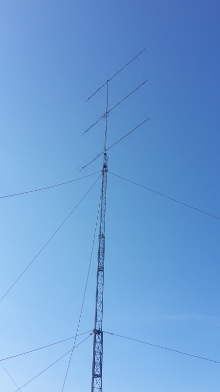
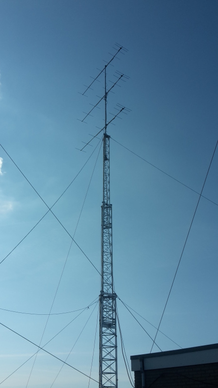
I received via email a number of questions about the 3 stack yagi construction that we use in the contest. This can be seen on the photos of two antenna systems below.
You do not see this much because most stations work with stacks with an even number of antennas.
The idea is not new and there are stations that have been using the 3 stack construction for decades.
The main reason why the 3 stack is used is that 3 2.3 wavelength antenna fits on a tube of 6m above the support bearing. The stacking distance to the antennae is about 3 meters.
It is just practical.
You could mount 4 antennas on the 6m mast. The antennas are then understacked. But in this case the gain is less than with 3 optimally stacked antennas. And you unnecessarily use more hardware. For the contest it would be better to stack more shorter yagies with a large opening angle. But the alround 2.3 wavelength is simply available. And a little gain is also useful in the contest.
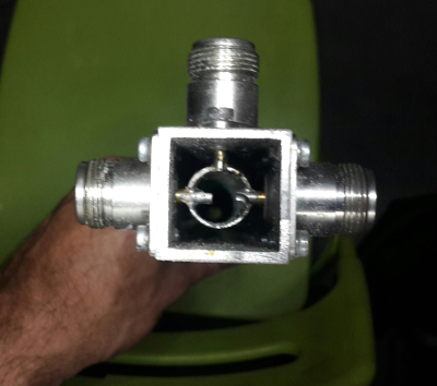
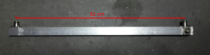
The construction of the coax splitter. The 3 antennas are brought to 1 point with 3 equal lengths of coaxial cable. There they are connected in parallel. I use ecoflex 10 cable. The impedance in that point is 50 ohm / 3 = 16.66 ohms. An impedance transformation must therefore take place from 50 to 16.66 ohms. This can be done with a quarter wave coax of 28.86 ohms. After all, sqrt (50 * 16.66) = 28.86 ohms. Een kwart golf is 300/144/4 = 0.52 meter.
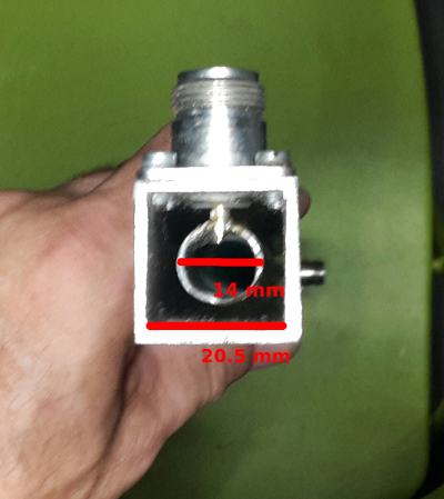
A quarter wave coax piece can be made of standard building material. The splitter I use is made of an aluminum square tube with an inner diameter of 20.5 mm. The inner conductor is made of a copper tube of 14mm outer diameter.
DL7YBN has a nice online COAX and Power splitter online calculator. If I fill in the values of the standard building material, an impedance of 27.46 ohm is calculated. This is enough close to the desired value.
Fig 3:
Fig 4:
Fig 5:
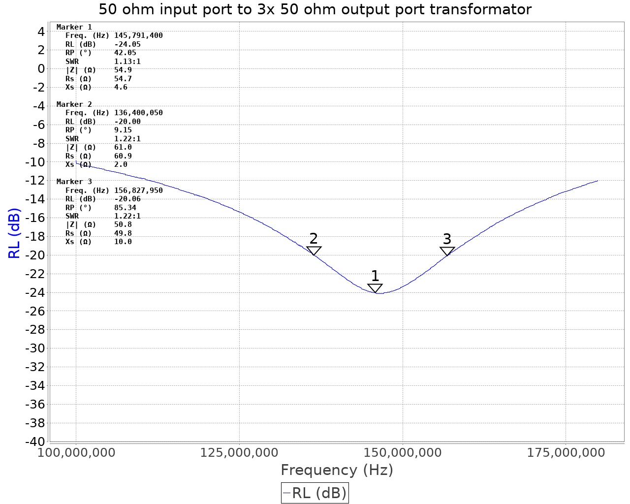
I measured the splitter with the miniVNA. The splitter is fairly broadband.
Fig 6: The 3 ports are closed with 50 ohms. The reflection attenuation is 24 dB @ 145MHz. This is an SWR of 1:1.13.
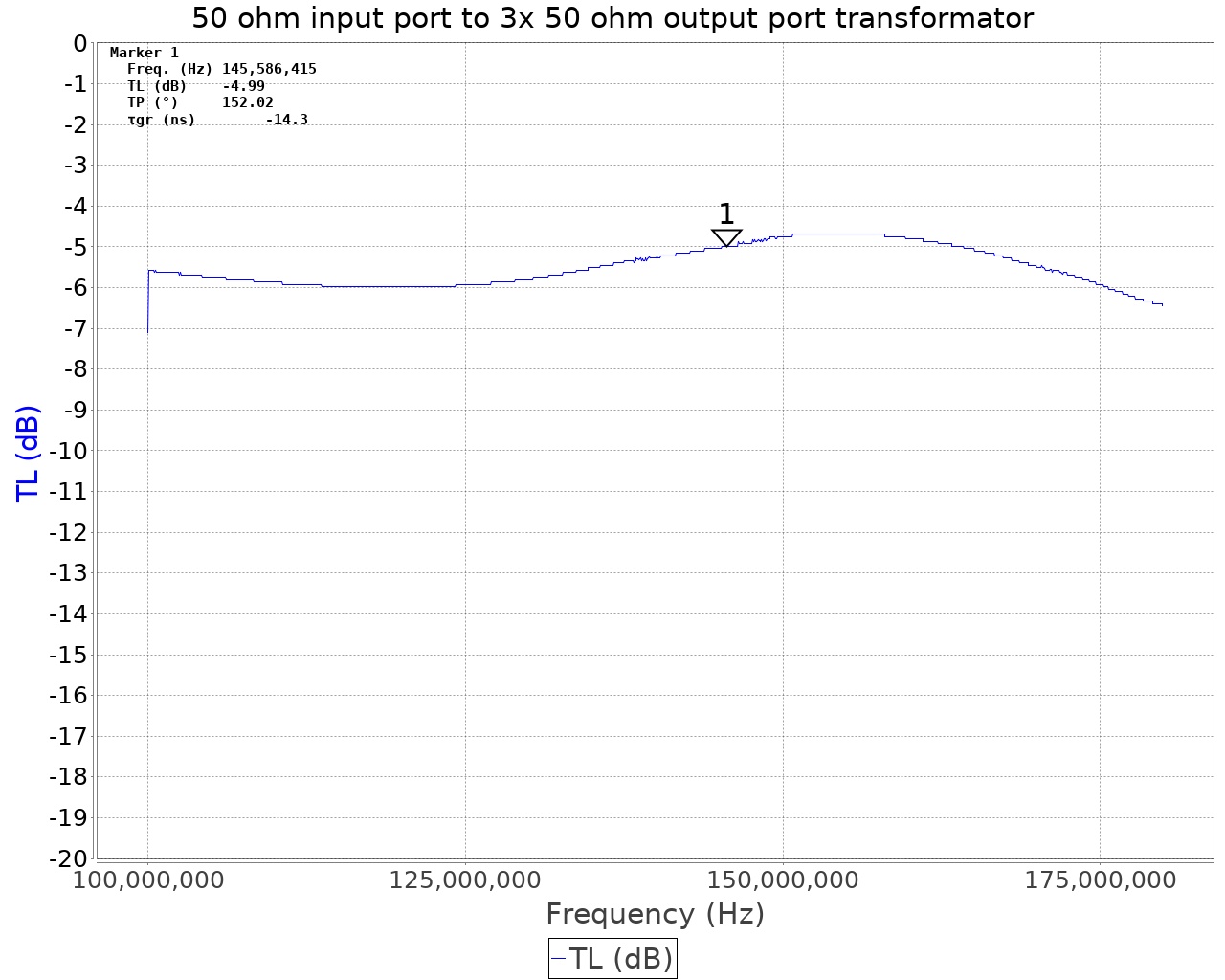
Fig 7: The transition attenuation is theoretically 1 watt input to 0.333 watts at one of the output ports. This is 4.77 db.
Measured is 4.99 - 0.2db = 4.8 db. Good enough.
One question was about how much power the splitter could handle. The maximum load is limited by the N-connectors. The power that an N-connector can handle is according to the specifications is 5kw at 20MHz and 500w at 2GHz. At VHF it will be somewhere between the maximum 1 and 2kW. So I suspect that this splitter can handle from 1 kw up to 2kw perfectly.